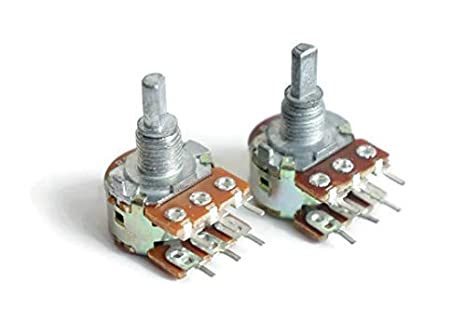
potentiometer Principle: In electronic circuits, a potentiometer is one of the most often used variable resistors. It’s a three-terminal gadget that helps control current flow and change resistance in a circuit.
WHAT IS A POTENTIOMETER?
A potentiometer is a three-terminal resistor. One of the three terminals is variable, while the other two are not. It’s an electric component that compares an unknown voltage to a known voltage, which can be obtained from a cell or any other supply source. In other terms, it’s a gadget that measures a cell’s EMF (electromotive force) and internal resistance.
A potentiometer can also be used to measure potential differences by varying the resistance. Although potentiometers are most commonly used to control volume in radios and other audio-related electronic devices, they are also used in the manufacture of electronic components that allow circuits to be adjusted to get the desired outputs.
Working Principle of a Potentiometer
The potentiometer is made up of L, a long resistive wire, and V, a known EMF battery whose voltage is known as the driving cell voltage. Assume a primary circuit by connecting the battery terminals to the two ends of L. The primary circuit is connected to the cell whose EMF E is to be measured on one end and galvanometer G on the other. It’s supposed that this is a secondary circuit.
The operating concept is based on the potential across any piece of the wire, which is linearly proportional to the wire’s length and has a uniform cross-sectional area with continuous current flow. The following is the derivation used to explain the working principle of a potentiometer:
V=IRV=IR (Ohm’s law)
Where,
I: current
R: total resistance
V: voltage
R=ρLAR=ρLA V=IρLAV=IρLA
Where,
⍴: resistivity
A: cross-sectional area
With ⍴ and A constant, I is constant too for a rheostat.
LρA=KLρA=K V=KLV=KL E=LρxA=KxE=LρxA=Kx
Where,
x: length of potentiometer wire
E: cell with Lower EMF
K: constant
Because the potential difference is zero and there is no current flow, the galvanometer G has null detection. As a result, x is the null point’s length. Knowing x and K can help you find unknown EMFs.
E=LρxA=KxE=LρxA=Kx
Let L1 be the null point length of the first cell with EMF E1 and L2 be the null point length of the second cell with EMF E2 because the EMF has two cells.
E1E2=L1L2
Potentiometer Types
Although all potentiometers have the same basic working principle and design, the geometry of the movable terminals differs. The wiper on most potentiometers rotates on an arc-shaped resistive substance.
The wiper does, however, slide linearly on a straight resistive strip in some other types of potentiometers. Potentiometers are divided into two forms based on the resistive strip concept: rotary and linear.
1. Rotary Potentiometer: This type of potentiometer features a wiper that spins across two terminals to change the resistance. Rotary potentiometers are classified into the following groups based on the number of times the wiper can be turned or rotated:
Single Turn: The wiper revolves only 3/4 of the way around and only does a single turn.
Potentiometers with many turns (five, ten, or more) are called multi-turn potentiometers.
Two pots are adjusted together using concentric shafts in a Concentric Pot.
Servo Pot: A servo pot is a motorised pot that is used to automatically modify or control a servo motor.
2. Linear Potentiometer: These potentiometers, often known as sliders, faders, or slide pots, have a wiper that slides on a straight resistive strip. These can be further divided into the following groups:
Slide Potentiometers: Slide potentiometers are high-quality potentiometers constructed primarily of conductive polymers.
Dual Slide Pot: This type of pot is used to calibrate two slide pots at the same time.
Multi-turn Pot: This type of potentiometer is constructed by using a spindle, which actuates the slider.
Motorized Fader: A motor controls the resistance and movement of the wiper in this pot.
Application of Potentiometer
- A potentiometer is a voltage divider that can be used in a variety of ways. The following are some of the uses for pots:
- Audio Regulate: Both rotary and linear potentiometers are used to change and control the volume and other audio signals in audio devices.
- The pots are used to modify the brightness, colour, and contrast of the picture on televisions.
- Pots are also employed as servomechanisms, which are position feedback devices that are utilised to build a closed-loop control system.
- Pots are used in the design of displacement transducers because of their ability to produce huge output signals.
Potentiometer Symbol
A potentiometer is represented by a typical resistor symbol with an arrow. Because a pot is a three-terminal device, the arrow isn’t superimposed on the resistor symbol like it is on a variable resistor, but it is present as a third terminal.
